Vortex Flow Meter is one of several types of Flow Measurement where the author will discuss clearly what is a vortex flow meter, how does a vortex flow meter work, Vortex Flow Meter Application and how to install it? let’s see the review below here.
What is Vortex Flow Meter?
Vortex Flow Meter is a flow measurement device most suitable for flow measurement where the recognition of moving parts poses a problem. They are available in industrial grade, brass or all plastic construction. Sensitivity to variations in process conditions is low and without moving parts has relatively low wear compared to other types of flow meters.
Vortex Flow Meters operate under the vortex discharge principle, where an oscillating eddy occurs when a liquid such as water flows through a cliff body (as opposed to a streamline). The frequency with which the vortex is shed depends on the size and shape of the body. It is ideal for applications where low maintenance costs are important. Industrial vortex gauges are custom made and require the appropriate size for a particular application.
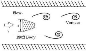
Vortex flow reading technology relies on measuring the number of vortex pulses generated by the bluff body immersed in the stream stream. The bluff body works inside the vortex flow meter. As the flow passes through this snapping body, vortices are generated on both sides of the snapping body. The flow rate can be determined by measuring the number of vortices.
History of Vortex Flow Meter
Theodore von Karman, a Hungarian-American physicist, was the first to describe the effect in which a non-current object (also called a bluff body) is placed in the path of a rapidly flowing stream, causing the liquid to alternately separate from the object. on its two downstream sides, and, when the boundary layer becomes detached and rolls back on itself, forming a eddies (also called eddies or eddies). He also noted that the distance between the eddies was constant and only depended on the size of the rock that formed them.
On the side of the cliff body where the eddies form, the fluid velocity is higher and the pressure is lower. As the vortex moves downstream, it grows in strength and size, and eventually disengages or disengages. This is followed by the formation of a vortex on the other side of the cliff body. The alternating vortices are placed at the same distance.
Vortex Flow Meter Design
Vortex Flow Meters are typically made of 316 or Hastelloy® stainless steel and include a cliff body, vortex sensor assembly, and transmitter electronics, although the latter can also be installed remotely. They are usually available in flange sizes from 1/2 inch to 12 inch. The cost of installing vortex meters is competitive with bore meters in sizes under six inches. Wafer body gauges (without flanges) have the lowest cost, while flanged gauges are preferred if the process fluid is hazardous or at high temperatures.
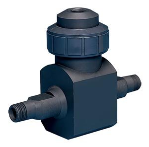
Bluff Body (square, rectangle, t-shape, trapezoid) and dimensions have been tried to achieve the desired characteristics. Tests have shown that linearity, low Reynolds number limit, and sensitivity to velocity profile distortion differ only slightly with the shape of the cliff body. In terms of size, the cliff body should have a width that is a sufficiently large fraction of the pipe diameter so that the entire flow participates in the discharge. Second, the cliff body must have a protruding edge on the upstream face to improve the flow separation line, regardless of the flow rate. Third, the length of the cliff body in the direction of flow must be a certain multiple of the width of the cliff body.
The majority of vortex meters use a piezoelectric or capacitance type sensor to detect pressure oscillations around the cliff body. This detector responds to pressure oscillations with a low voltage output signal having the same frequency as the oscillations. Such sensors are modular, inexpensive, easy to replace, and can operate over a wide temperature range–from cryogenic liquids to superheated vapors. The sensor can be placed inside the meter body or outside. The wetted sensor is directly stressed by the vortex pressure fluctuations and enclosed in a toughened case to resist the effects of corrosion and erosion.
An external sensor, usually a piezoelectric strain gauge, senses the eddy discharge indirectly through the force applied to the shedder blades. External sensors are preferred in highly erosive/corrosive applications to reduce maintenance costs, while internal sensors provide better range (better low flow sensitivity). They are also less sensitive to pipe vibrations. The electronics housing is typically rated explosion and weather proof, and contains an electronic transmitter module, termination connections, and optionally a flow rate indicator and/or counter.
Vortex Flow Meter Style
Vortex Flow Meter is an intelligent vortex meter providing a digital output signal that contains more information than just flow rate. The microprocessor in the flowmeter can automatically correct for insufficient straight pipe conditions, for differences between bore and mating pipe diameters, for cliff body thermal expansion, and for K-factor changes when the Reynolds number falls below 10,000.
Smart transmitters are also equipped with diagnostic subroutines to signal components or other failures. Smart transmitters can initiate routine tests to identify problems with the meter and application. This on-demand test can also assist in ISO 9000 verification.
Some vortex flowmeters can detect mass flow. One such design measures the frequency of the vortex and the strength of the vortex pulse simultaneously. From these readings, the density of the process fluid can be determined and the mass flow calculated in the 2% range.
Other designs are equipped with multiple sensors to detect not only the vortex frequency, but also the temperature and pressure of the process fluid. Based on that data, it determines the density and mass flow rate. The meter offers 1.25% rate accuracy when measuring mass flow of liquids and 2% rate accuracy for gases and vapors. If knowledge of process pressures and temperatures is useful for other reasons, these meters provide a convenient and less expensive alternative to installing a separate transmitter.
Vortex Flow Meter for Corrosive Liquids
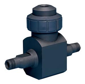
With no moving parts, all electronics are housed in a corrosion-resistant enclosure. Unlike meters containing metal or moving parts, plastic vortex meters are particularly suitable for aggressive or easily contaminated liquids. Applications range from ultra-pure water to highly corrosive chemicals and slurries.
Industrial Vortex Flow Meters
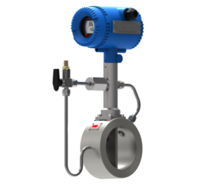
Measures Vapors, Gases and Low Viscosity Liquids. The vortex generated by the flowing fluid exerts pressure on the shedder rod in the form of pulses, and the shedder rod transmits voltage pulses to the encapsulated piezoelectric sensor.
Vortex Shedding Flow Meter
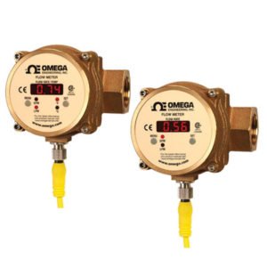
Operating under the same eddy discharge measurement principle, this type of eddy flow meter is suitable for fluids such as thick, clean or dirty water which is compatible with brass, PVDF and FKM. These applications are found in most process industries, including rubber, steel, fabrication, manufacturing, refining, paper, chemical, food, petrochemical, and electricity. Not suitable for flammable liquids or gases such as air.
Vortex Flow Meter Working Principle
The working principle of the Vortex Flow Meter and the workings of the Vortex Flow Meter are in accordance with the Karman Vortices principle. When a bluff body is placed vertically in a pipe, as the fluid flows around the bluff body, a column of regular vortices will be generated alternately on each side of the bluff body (shown in Fig. 1), these eddies are known as “Karman Vortices”. Vortex Flow Meter Working Principle and How it Works Vortex Flow Meter has a resistance section that releases vortices called “bluff body”. The frequency of discharge of the vortices is related to the velocity of the liquid. Expressed by the following formula:

Therefore How Vortex Flow Meters Work: frequency —- of shedding Karman Vortices
- Sr—-Strouhal number
- U—-average speed in pipe
- d—-face width entrance cliff body
- m—-the ratio of the total flow-area on both sides and measure the pipe section area
- U1—-average speed on both sides of the bluff body

That’s why the Vortex Flow Meter works: D —- pipe inner diameter
d —- bluff body inflow face width (unit: mm)
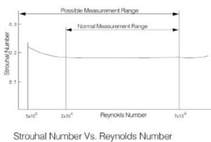
The strouhal number is related to the bluff body shape and the Reynolds number (shown in graph 2). From the graph, Sr is essentially constant when the range of the Reynolds number is ~.
QFormula of instantaneous volumetric flow as below:

The K meter factor formula is as below:

Therefore : q —- volumetric flow through the flow transducer (unit: m3/s)
- f—-vorticity frequency (unit: Hz)
- k—-vortex transducer flow factor meter(unit:m)
- U—-average speed in pipe (unit: m/s)
Exhibit 2 shows that the volumetric flow rate of the vortex flow meter is proportional to the frequency of the vortices. The K factor meter is only related to the bluff body geometry parameter, not related to the physical characteristics of the fluid and materials.
The general formula of the vortex flowmeter in the project is as below:

- Therefore: f —- releases the frequency of Karman Vortices (unit: Hz)
- q—-volumetric flowrate (unit: m3/h)
Strouhal Sr Number Introduction:
Strouhal number is a very important factor in Vortex Flow Transducer. Within a certain range of the Reynolds number, the Strouhal number approaches a constant. In the range of the straight region Sr≈0.17 in the curve (shown in graph 2), the frequency of discharge of the vortices is proportional to the velocity, so that as long as the frequency (f) is detected, the velocity (v) will be obtained, and the volumetric flowrate will be obtained according to v.
When the fluid flows in the pipe and the Reynolds number is between ~, the Strouhal number is considered as a constant, which can guarantee the accuracy of the measurement range. If outside the Reynolds number range above, Sr will increase as the Reynolds number decreases or increases, nonlinearity will occur. When the Reynolds number decreases from to, even though the vortices are shed, the measurement accuracy will decrease, because it is nonlinear. So the Reynolds number ~ will be referred to as the measurement range of the Vortex flow transducer. that’s how a Vortex Flow Meter works and the working principle of a Vortex Flow Meter.
Vortex Flow Meter Applications & Limitations
For Applications Vortex Flow Meters are not usually recommended for batching or other intermittent flow applications. This is because the dribble flow rate setting of the batching station can fall below the meter’s minimum Reynolds number limit. The smaller the batch total, the more likely it is that errors will be generated.
Low pressure (low density) gases do not produce a sufficiently strong pressure pulse, especially if the fluid velocity is low. Therefore, it is most likely that in such a service the range of the meter will be poor and low currents will not be able to be measured. On the other hand, if the drop in range is acceptable and the meter is measured correctly for normal flow, a vortex flowmeter can still be considered.
If the process fluid tends to coat or accumulate on the cliff body, as in the application of a vortex flow meter to slurries and slurries, this will eventually change the K factor of the meter. The eddy discharge flow meter is not recommended for such applications. However, if the dirty liquid has only a moderate amount of non-coating solids, the application is likely acceptable. This is demonstrated by a 2 year test on limestone slurry. At the end of the test, the K factor was found to have changed only 0.3% from the original factory calibration, although the cliff body and flow tube were badly damaged and perforated.
When measuring multi-phase flow or vortex flow meter applications (solid particles in gas or liquid; gas bubbles in liquid; liquid droplets in gas), the accuracy of the vortex meter will drop due to the meter’s inability to distinguish between phases. The application of a vortex flow meter to low-quality wet steam is one such application: the liquid phase must be uniformly dispersed in the vapor, and vertical flow lines must be avoided to prevent slugging. When the pipe is in a horizontal position, the liquid phase tends to flow at the bottom of the pipe, and therefore the inside of the pipe must remain exposed at the bottom. This can be achieved by installing the cliff body horizontally. The measurement inaccuracy in such applications is about 5% of the actual flow, but with good repeatability.
The permanent pressure loss through the vortex meter is about half that of the orifice plate, approximately two speed heads. (The height of the velocity is defined as V2/g, where V is the flow velocity and g is the constant of gravity in consistent units.) If the pipe and meter are the exact same size, the pressure drop may be only a few psi. However, downsizing (installing a meter that is smaller than the line size) to increase Reynolds can increase head losses by more than 10 psi. We must also ensure that the venous contracta pressure does not fall below the vapor pressure of the process fluid, as this will cause cavitation. Naturally, if the back pressure on the meter is below the vapor pressure, the process fluid will flash and the meter reading will be meaningless.
The main advantages of the vortex meter are its low sensitivity to variations in process conditions and low wear relative to the orifice or turbine meter. Also, the initial and maintenance costs are low. For this reason, they have gained wider acceptance among users.
Installation Recommendations
When installing a vortex flowmeter in an existing process where the flow range is unknown, it is recommended to first take some approximate measurements (using a pitot ultrasonic device or a portable clamp). Otherwise, there is no guarantee that the line size vortex meter will work at all.
Vortex meters require a well-developed and symmetrical flow velocity profile, free from any distortion or eddies. This requires the use of straight up and down pipes to condition the flow. The length of the straight pipe should be equal to the meter and the length should be nearly the same as that required for mounting holes with a beta ratio of 0.7. Most vortex flowmeter manufacturers recommend a minimum of 30 pipe diameters downstream of the control valve, and 3 to 4 pipe diameters between the meter and the downstream pressure tap. The temperature element should be small and located 5 to 6 diameters downstream.
About half of all vortex meter installations require the “shrinkage” of large process pipelines by concentric reducers and expanders. Even if a flow straightener is installed, some straight (relaxation) tubing will still be required.
The vortex meter can be installed vertically, horizontally, or at any angle, as long as it remains flooded. The meter can remain waterlogged by mounting it on a vertical upward flow line. When installing the flowmeter in downward or horizontal flow, the downstream pipe must be kept high. Check valves can be used to keep pipes full of liquid when there is no flow. Block valves and bypass valves are required if sensor replacement in a particular design requires stopping the flow and opening the process.
Mating flange (on schedule 40 or schedule 80 mating) must have the same diameter and bore as the flowmeter. Weld neck flanges are preferred, and reducing flanges shall not be used. The inner surface of the mating pipe shall be free from grinding scales, holes, holes, reaming scores and bumps for a distance of 4 meter upstream diameter and 2 meter downstream diameter. Meter holes, gaskets, and adjacent pipes must be carefully aligned to remove any obstructions or steps.
Excessive pipe vibration can be eliminated by supporting the pipe on either side of the meter, or by rotating the meter so that the sensor is moved out of the vibration plane. Process noise due to chattering valves, steam traps, or pumps can result in high readings or non-zero readings under zero flow conditions. Most electronic meters allow for increased noise filter settings, but increased noise reduction usually also decreases the meter’s low flow sensitivity. One option is to move the meter to a less noisy part of the process.
Thus the article about “Vortex Flow Meter: Understanding, Working Principles, and Installation” hopefully can answer all questions from readers and add insight to related articles, hopefully it will be useful.
